Scopes are complicated, but let's try to simplify them without "dumbing them down":
This is a diagram of the OPTICS inside a simple scope. Fixed magnification, no parallax adjustment:
This is a diagram of the OPTICS inside a simple scope. Fixed magnification, no parallax adjustment:
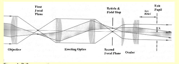
In this first image, to the left is the target, the rays of reflected light bounce from the target and enter the Objective lens. This lens (a doublet in the illustration because it is made of two "nesting" lenses) focuses the image onto the First Focal Plane. But it is an INVERTED image.
So, the image then impinges into the "Erecting optics", these turn the image right side up, again using a set of doublets.
Now that the image is right side up, this manufacturer chose to "inject" the reticle image at this point, making this scope a SECOND Focal Plane scope.
In order to provide crispness to the image, scope manufacturers insert a "stop" (a metal plate with a hole) at this point. This reduces the stray light bouncing around the internals of the scope and allows the eye to perceive a "crisp" sight picture. It does not diminish light throughput because the image is already a reduced one and it already includes the reticle.
Now the image goes into the Ocular assembly that is a system of a singlet and a doublet. The focal distances of these lenses are long and therefore there is not enough distance to invert the image, it just gets magnified. The magnification is given by the distance BETWEEN the singlet and the doublet. Longer distance, less magnification; shorter distance, more magnification. In a fixed mag scope like the one in the figure the magnification is set at the factory and it cannot be changed without disassemblying the scope.
Higher magnifications also mean reduced eye relief. Dis-assembly of the scope and readjustment of the distance between the ocular elements allows for increased magnification at the cost of reducing eye relief.
This is housed inside a mechanical housing that has its own complications, again a simple scope, but this one an old Zeiss with a FIRST Focal Plane reticle:
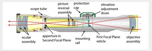
In this illustration the target is to the RIGHT. The image of the target and the reticle coincide onto the FFP, and that gets inverted.
You will note that now we have a screw that puts downward force against a leaf spring we cannot see on the other side of the "picture reversal assembly", also known as the Erector Assembly. You will also note that the Erector (or Picture Reversal) assembly is held in pivots at the junction of the scope's tube and the ocular tube; where the Second Focal Plane Aperture (Stop) is located.
By TILTING the lenses, the image moves and with it, the reticle. Thereby moving the POA relative to the axis of the Scope's external body.
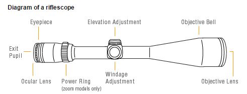
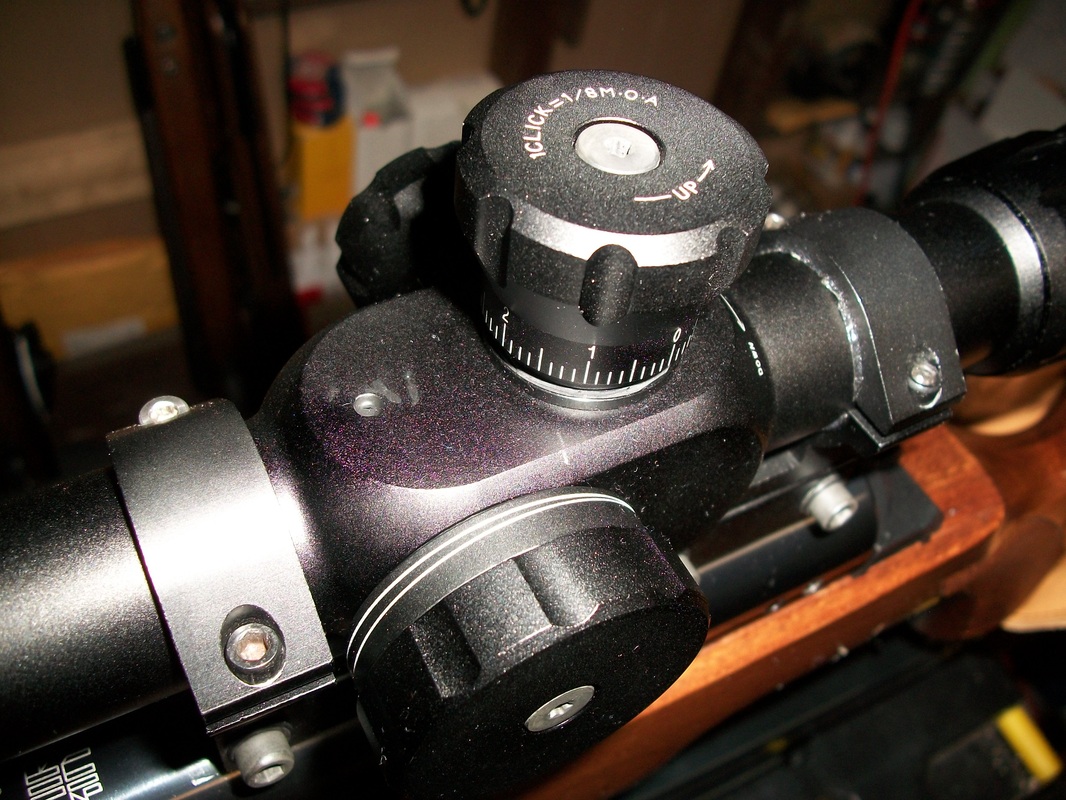
Of course all we see is the externals:
You will note that now we have a screw that puts downward force against a leaf spring we cannot see on the other side of the "picture reversal assembly", also known as the Erector Assembly. You will also note that the Erector (or Picture Reversal) assembly is held in pivots at the junction of the scope's tube and the ocular tube; where the Second Focal Plane Aperture (Stop) is located.
By TILTING the lenses, the image moves and with it, the reticle. Thereby moving the POA relative to the axis of the Scope's external body.
Of course all we see is the externals:
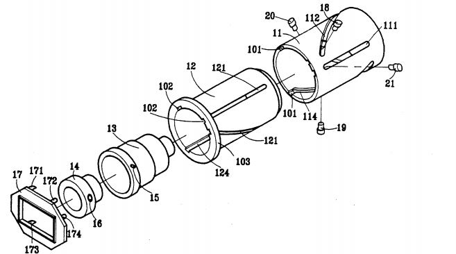
Now, when we have a variable mag scope we get another set of mechanics inside the scope, to be more precise, inside the Scope Tube, connected to the Ocular/Eyepiece tube, this set is, USUALLY, something like this:
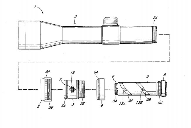
What you see here is the "barrel" (piece #9) that gets locked into the Zoom Collar (piece #3) and that because it has two slots (9a and 9b) that have a different "pitch" where the pegs (pieces 12A and 12B) that support the two lenses in the Ocular system, now can get closer to each other, or get separated with the turn of the collar, change the magnification. This is the zoom unit. But keep in mind that this mechanism is not dissimilar to the paralax adjustment system when using a sidewhell.
So, having laid down a "language" with which we can try to understand the whole mess, let's dive into it.
Those of us that have used the old style "pirate spyglass", know that you bring your subject to focus by changing the length of the scope.
So, having laid down a "language" with which we can try to understand the whole mess, let's dive into it.
Those of us that have used the old style "pirate spyglass", know that you bring your subject to focus by changing the length of the scope.
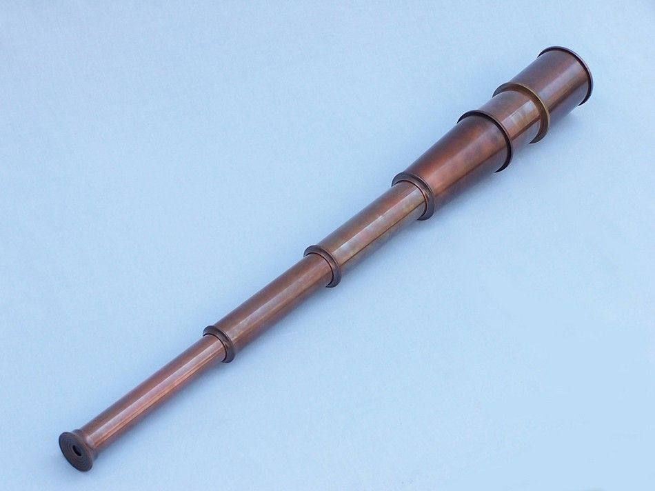
Well, riflescopes are not different. To bring the object into focus you need to change the length of your scope. But a rifle scope has no "telescoping barrels", so how do we do it?
One way is to move the Objective lens assembly. Like the old Benchrest scopes where the WHOLE assembly moved:
One way is to move the Objective lens assembly. Like the old Benchrest scopes where the WHOLE assembly moved:
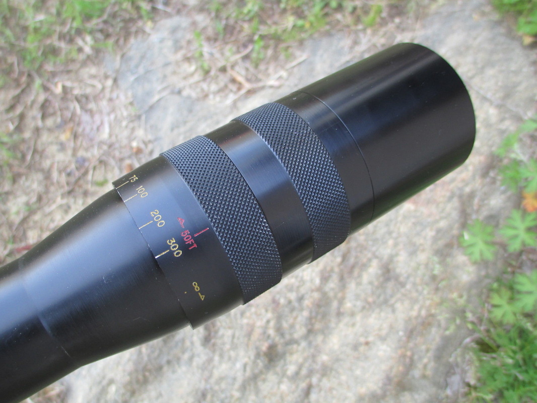
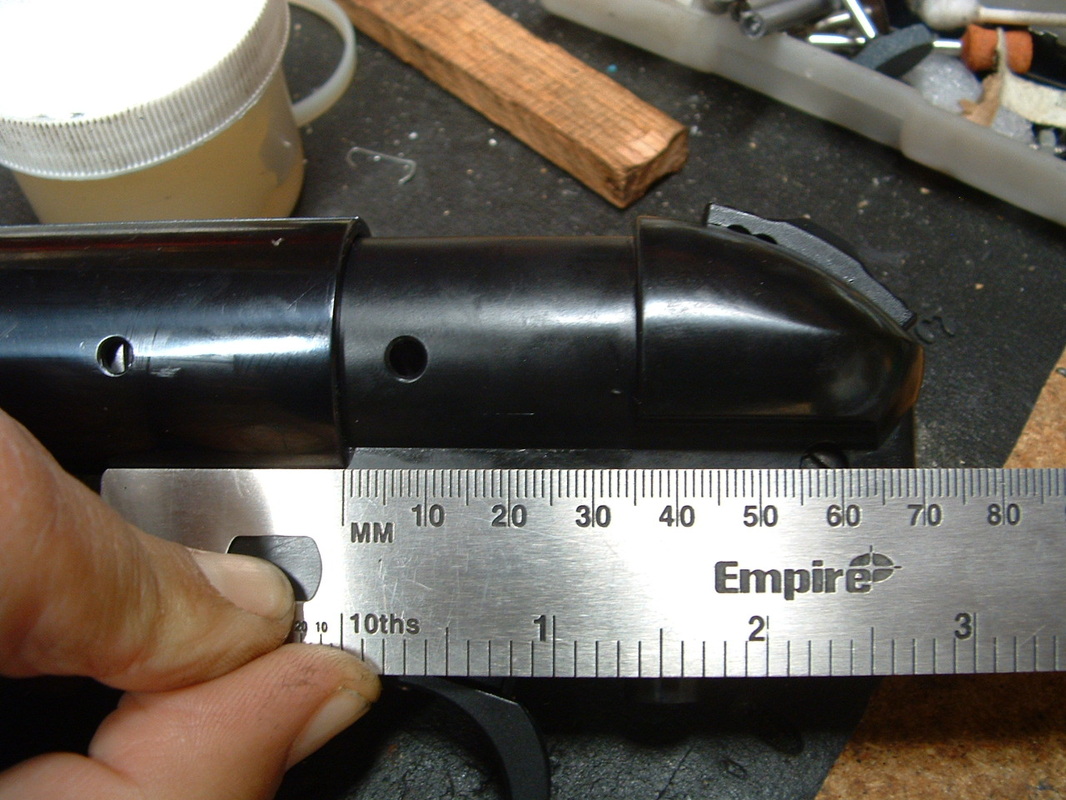
That posed problems for waterproofing, and so the manufacturers turned the whole moveable thing into a sealed unit, like the Vortex optics one:
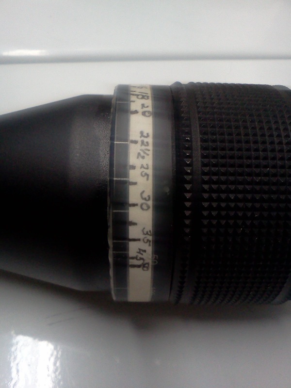
Some manufacturers, like Leupold (in their EFR models) and Sightron (in their BigSky II) have even gone to the trouble of making the AO a barrel within a barrel assembly, whereby you turn on a ring that is sealed; that ring, in its turn, turns a sleeve that holds the lenses in an assembly similar to the Zoom barrel with pegs holding the lenses and those pegs riding on pitched slots.
Many years ago, John Unertl made a scope he called "the Programmer", because the pitch of the slots was made in such a way that uniform rotations yielded uniform focus distance changes. Alas there was no FT way back then and the feature had no value for the shooters. So it was dropped as it was expensive to incorporate. Nowadays Unertls can fetch upwards of $800 and Programmers in particular are so scarce that no collector is letting anyone shoot his, or releasing one into the real world.
Now, ¿WHY do the slot in the Programmer had to be SO COMPLICATED?
The answer lies in this graph:
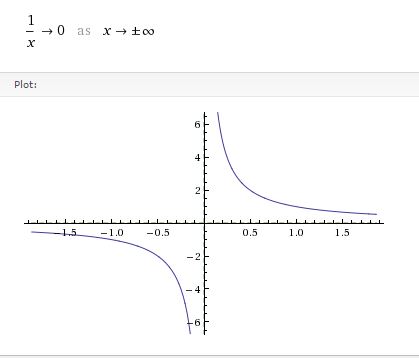
This is the inverse graph, the one that relates the distance of movement of the lens to the change in distance of objects in focus.
Forget the bottom left quadrant and focus (pun intended) on the top right quadrant. Think that the horizontal axis is the distance to the object you want to focus, and that on the vertical plane you have the position that the Objective lens has to be at relative to some reference in the scope, to focus at that distance. Let's just think of the vertical axis as being in mm's and the horizontal axis being in "Chains" (twenty meters approx):
If you change the objective lens position from 5.0 to 2.0. you have now changed your focus from objects that were in position 0.2 Chains to position 0.5 Chains; a movement of 0.3 Chains on the distance scale needed a movement of 3 units on the objective lens position. Or, in other words, when an object moves from being 4 meters (0.2 Chains) to being 10 meters (0.5 Chains) away, you need to move the objective 3 mm's.
If you now want to focus on objects that are now in position 1 (20 meters), you now move the objective lens from position 2.0 to position 1.0, PLEASE note that 1 mm's of Objective lens movement has moved the focus point 10 meters from 0.5 chains to 1 chain.
NOW, If you want to focus on objects that are at position 2.0 (40 meters), then you only need to move the ocular lens ½ mm to position 0.5.
You have moved the focus from 20 meters to 40 meters with only ½ mm's of displacement of the lens.
If the object moved to 80 meters (4 chains), then the Objective lens moves to ¼ mm's.
"Ranging" farther and farther becomes harder and harder.
You might say "We ALL knew that DUUUUUH!", perhaps. But now you know WHY.
Furthermore, what is true of absolutes is also true of relatives, and here comes an important conclusion: Small irregularities on the lens surfaces are nothing more than additional lenses in the optical path. So the lesser the quality of the lens, the HARDER UPON HARDER it will be to obtain a good rangefinding.
So, now that we understand how AO scopes work and why the marks get closer and closer as the distances get longer and longer, how does a sidewheel scope does it?
In modern Sidewheel scopes, most of the times, we have a much larger "saddle", the big block that holds together the front tube and the back tube, or in monoblock scopes, the large bulky housing in the middle.
Inside that "saddle", there is an axle and a cog wheel, something like this:
Inside that "saddle", there is an axle and a cog wheel, something like this:
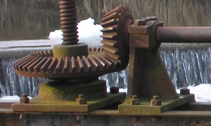
I said something LIKE THIS, not exactly like this! LOL!
Anyway, there is inside a small version of these sluice gate opening mechanism.
The sidewheel turns an axle that then turns another gear that spins the sleeve that has the pitched slots that hold the pegs that hold the lenses.
In sophisticated scopes, the complete arrangement will be substantially more complicated to remove slack and play and inaccuracies, they can use Spiral teeth and Hypoid alignments, springs and all sorts of devices to remove, as much as possible, the slack and the backlash.
Yes there are good scopes, but NONE are completely independent of slack and backlash.
If now I may recall your attention to the pitched slots in the barrel and the concept of the Programmer scope, it is not a large leap to understand that there are ways to cut the slots so that the sidewheel itself gets MORE resolution at certain points in the rotation than in others. You can use a bigger pitch for the "close" distances and progressively fine pitches for the longer distances.
IOR, March, S&B, Leupold, and others have used this concept. Problem when dealing with THIN tubes with slots cut into them made out of relatively light and easy to machine materials is that the TEMPERATURE CAN wreak havoc with all the maths that went into the design.
What we, shooters, have done is to "help" the sidewheel do its job. The advent of larger and larger sidewheels is a clear indication that DISTANCE along the sidewheel tape is more important to the shooter than angular displacement.
Some of us are working in offset center wheels, or logarithmic wheels that take into consideration the need for length on the tape as the needed angular displacement is reduced for small increases at long ranges.
There is always the possibility to leap forward by taking a step back. There is at least one manufacturer that offers a 720º revolution AO, and that offers very interesting possibilities as the distance progression can be spread over twice the angular distance, this creates, theoretically, twice the linear space to place all the distances. We'll be testing that theory soon.
So, to conclude:
A scope has mechanical and optical parts. They BOTH have to work well to give good results.
The mechanical part is currently the limitation to the performance. The machining of consistently high quality pieces with precision in the 0.0001" makes for expensive methods, setups, labour and materials. Glass has become inexpensive in relation to the mechanical parts. High quality glass is, and always will be, expensive, VERY few scopes use REALLY Top Tier Optics, those that do usually pair up with mechanisms that are commensurately precise, so expense comes back into the picture.
What will the future bring?
Probably a discontinuity. Video scopes are advancing at leaps and bounds. And once you get high quality glass with HD CCD's, the resolutions possible exceed human vision acuity with ease. And the jump from there to fully computerized, electronic scopesight/video/GPS device is relatively simple.
Unless you are like me, a confirmed masochist that wants to "make do" with "squirrel guns" and "common scopes", perhaps you owe it to yourself to buy at least one REALLY GOOD scope. But . . .
that is up to you.
;-)
Keep well and shoot straight!
 RSS Feed