Connecticut Custom Airguns
  • Welcome!
  • Hector's Airgun Blog
  • Products and Products Blog
    • One-Off's
    • The "Héctors Special'" scope by Sightron
    • K1050i FT
    • The Hex Louver or "Secret Sunshade"
    • Pellet Path Calculator >
      • Questions, Answers and Comments on P-P Calc
      • Privacy Policy for PP-Calc
    • The Nautilus SideWheel
    • The X-10 TiltMeter
  • Zimmer-Silhouetten
    • Results 2017-2018
    • Results 2016-2017
    • Results 2015-2016
    • Results 2014-2015
    • Results 2013-2014
  • References and Links
  • Contact us
  • Store

Hector's Airgun Blog

Where we discuss, CIVIILY,  anything airgun.

Return Home

Shot cycle Dynamics in 3 Spring-Piston Airguns.- Preface

4/1/2021

11 Comments


A nine+1 entry series by John Cerne, Yogi, and Hector Medina

Another title could be: "Conversations between three passionate airgunners: a scientist, a profound observer of life and great admirer of beauty", and an engineer.

Or, we could even have a joke: "A scientist, a 
yogi and an engineer enter a bar . . "

Truth is these blog entries (we THINK we will stop at 9) that we plan on publishing every fortnight, started as a casual conversation; not in a bar, but in a forum; were then taken to PM's, and when the project really started to flesh out, formal EMail's started flying all around.

We formally convened on Valentine's Day 2020, and it was truly an auspicious day because everything has gone reasonably well. It has been a pleasure, and a great privilege, to work with these two gentlemen over the last 13½ months.

So, let me introduce my friends to you.

The originator of all this was my friend "WL", who chooses to use ONLY the nick/handle "Yogi", both here and when posting in the GTA forum; he had some very pertinent questions about transfer port (TP for short) geometry (diameter, orientation, length) and when I explained my theories, he ventured the idea of underwriting the effort to ship different guns to different people that could study and explain the possible relationships.

At about the same time, John Cerne, who uses the nick/handle "JohnC" when posting in the GTA, came up with the idea of looking into the overall dynamics of the shot cycle in spring-piston guns.
Now,
John has a PhD in experimental condensed matter physics and is a physics professor at a well known research university so, his participation was an opportunity that was too precious to let go.
He was very enthused with some experiments by Jim Tyler on measuring recoil motions in airguns, which were published in the British "Airgun World" magazine..

On my side, I had recently finished the collaboration with Steve Herr (NitroCrushr) about the Four Part "Saga of a DIANA 56 T/H" and, as closure of that report was the receipt of Steve's sled. I hadn't had time to study in detail how to expand its functionalities, so the project proposed by John seemed a suitable vehicle with the ideal candidate. I proposed the joining of forces to all three parties, with the caveat that the TP geometry aspect would be looked at just tangentially, still, Yogi was generous enough to help us get everything underway.

And so it is that we (99% John) have been working in these ideas, developing the tools to START interpreting and understanding the REALITIES behind the APPARENTLY simple mechanical devices we love (and sometimes hate) that are spring-piston airguns.

We FULLY REALIZE this is just the beginning of a new conceptualization. And we realize that we will not do it all on our own. So, part of the intention of this NINE part series is to give (in the spirit of the 1950's "Popular Mechanics" magazine) almost anyone with a modicum of common sense and practical skills, the knowledge and understanding to make up HIS/HER OWN research devices/apparatus, and enable them to start researching into the phenomena that actually make our airguns what they are, what gives them "character", what makes them "tick".

We also HOPE that the industry realizes that the shooters are becoming more and more sophisticated, and that some "Benchmarks" CAN be set that are quantitative and hard-data based enough to dispel all the mystery and "dark-arts" atmosphere that surrounds the "tuning" of spring-piston air rifles, or the qualities of a design.

Now, regardless of how much science you want to put into anything, NOTHING regarding human interaction with machines is written in stone (or parchment / paper). It is not a dogma of faith. Because we, humans, are vastly different. So, we don't purport to have arrived to the ideal recipe for a gun that will work for everyone, but we do think that measuring some key aspects of the shot cycle should enable users to select better the gun that will suit them; and allow manufacturers to come up with better products.


I know that, in a way, we cheated. Why? because we chose for this exercise three of the best examples of spring-piston airguns of all times (Walther LGU, Walther LGV and FWB 124). We know that the dynamics in these three highly tuned airguns are as good as they can get, AND we had the added advantage that the Walthers are basically the same rifle, just one uses the barrel as a cocking lever, the other has a fixed barrel and a separate cocking lever.
​BUT, in our defense, we will say that this also allowed us the tangential look into the TP geometry, since one (the LGV) has a long transfer port and the other (the LGU) has a short one.

The nine parts of this series are:
Chapter 1. Diagnostic equipment: How can we understand better what our air rifles are doing? 
Chapter 2. How do the Walther LGU, Walther LGV and FWB 124 compare?
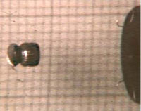
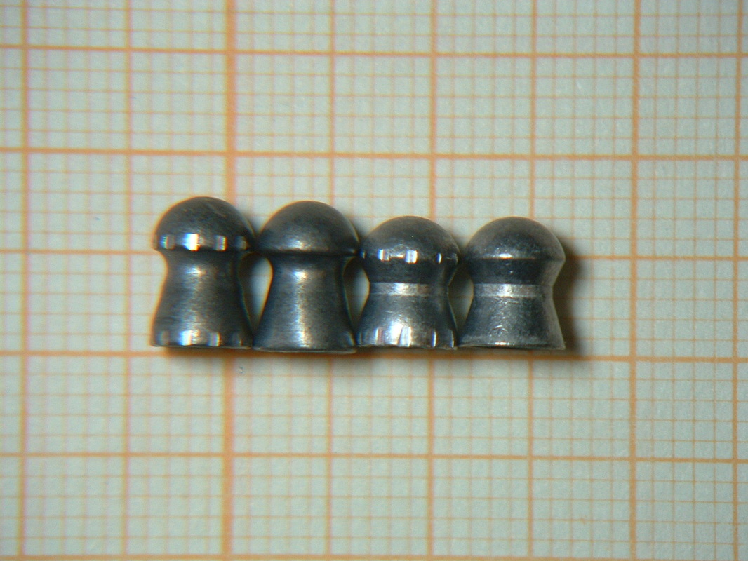
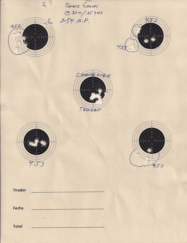
Chapter 3. Group statistics: What can target groups tell us about the accuracy of an air rifle?
Chapter 4. LGU/LGV powerplant swap: How does swapping airgun pistons and springs in an LGU and LGV affect performance? 
Chapter 5. Does Krytox improve performance?
Chapter 6. Does more mass in a springer air rifle result in better accuracy?
Chapter 7. Does a higher energy spring decrease accuracy in a springer air rifle?
Chapter 8. What happens when you remove the LGU’s muzzle cap?
Chapter 9. Conclusions: What does this all mean?
​
So, without further ado, I yield the floor to John Cerne.
11 Comments

At the Moment of Firing and Fit of pellet to the rifling

1/19/2016

28 Comments

 
INTRODUCTION.- One of the most misunderstood aspects of airgunning is the series of small, but important events that take place at the moment we pull the trigger.
Firearms enthusiasts know well the series of events that transpire inside the brass case the moment the trigger is pulled, but let us review them for the sake of those that are not so familiar with powder burners: the firing pin impacts the primer, the pre-stressed mixture ignites, sending a jet of very hot gases through a small hole into the main/powder charge cavity of the case where the granules of smokeless or the flakes of black/synthetic powder ignite in a somewhat random fashion. The further high temperature and pressure of the gases defeat the coating of the granules and ignite them in somewhat of a chain reaction. This makes the pressure inside the case soar to levels that are high to really grasp in our normal everyday mind as we never encounter in our everyday lives things that work at between 16,000 and 55,000 pounds per square inch (PSI).
Just to put that into perspective: imagine in your mind’s eye a 27 ton Sperm Whale (like Moby Dick) standing on its nose supported by a steel billet that is 1” on each side, square.
If you think Uncle Ted stepping on your toes was bad this last Christmas, I can assure you this would be many times worse.

So, there is a lot of pressure, and that pressure impinges on the BASE of the bullet. That base may be solid, or hollow; flat or boattail, but in general we are talking of something substantial and even the Minnie style hollow base bullets are solid at most 1/6 of the way forward. Yes lead is “soft”; anywhere from Brinell 5 to Brinell 22, and if it is a jacketed bullet, then you are talking of Brinell 35-125 (if the jacket is pure copper - gilding metal). Main point to remember here is that NOTHING in the firearms world approaches the softness of a skirted pellet that is hollow almost halfway through its length and made of alloys that, in the hardest of cases, contain still less than 3% antimonium (non-lead pellets are different, and while those require special attention, they still are much softer than the softest jacketed or plated bullet).
But, let’s go back to the point where gases are starting to impinge on the base of the bullet, and this pressure, exerted over an area means a force. The force created thus pushes the bullet out of the case, pushes the case walls out into the chamber walls and seals the neck of the brass case to the steel neck of the chamber, thereby providing a really good seal. This is what keeps us safe from all the mayhem inside the brass case when we shoot.
The bullet is forced forward VERY rapidly. So rapidly that the front section of the bullet does not want to move and this forces the rear section of the bullet to expand into the rifling, sealing the gases behind. If the bullet is solid, there is little “upset” as this phenomenon is called, but if the bullet is hollow based or soft, this upset has to be taken into account when designing the bullet. Some is good, too much might not. For a short while, under these pressures and forces, the metal of the bullet is in almost a malleable/fluid state; and in a short time after this, the front of the bullet finally gets accelerated and also upsets, filling the rifling completely.
In the cast bullet world, it is generally understood that bullets have to fit within 0.001” of the LAND / CALIBER / GROOVE diameter, and that the hardness of the alloy has to be such that no material gets stripped off the projectile and gets embedded into the rifling. At present, we do not use as many rifling designs as we used to: Pope, Forsyth, Alex Henry, Segmental, Obermeyer, Ballard, Green, Ratchet, MicroGroove, Enfield, Polygonal, Elliptical, Whitworth and a host of other styles, but, for the present, the list is quite shorter: MOST airgun manufacturers will use the land and groove style with equal angular spreads for lands and grooves called Enfield or Ballard or the Polygonal style now in use by Lothar Walther barrels, VERY FEW manufacturers will go to the trouble of designing a barrel for a specific projectile, as it has been proven that the general style does work over a wider range of speeds, shapes, materials and duties.
The exception, of course, are those barrels designed for military projectiles (where the potential of a government contract makes sense to go through the development process) and, to our knowledge, the 0.20" cal CCA barrel designed specifically for the JSB 13.7 grains Exacts (and made by Lothar Walther).
The MAIN duty of the rifling is to swage the projectile to its final shape and make it turn.
Why so many styles for such a simple duty? you may ask. 
The reality is that the design of the rifling is also responsible for a number of things:
How much energy is needed to get that projectile swaged to its final shape?
How much interference there is between the original shape and the final shape and therefore, how much cleaning the barrel will need.
How UNIFORM can the barrel be built or made.
For a time, I experimented a bit with the Forsyth rifling (in airguns also known as the "Career" rifling. But that experiment, alas, was not as successful as I wanted. And yet it produced an interesting result (more on that later).
Picture
IN THE AIRGUN WORLD.- What happens is, perhaps less dramatic from the numbers and units standpoint, but given the SHAPE of the classic Diabolo Pellet, the proportion of forces, pressures and temperatures (especially in the spring-piston airguns), AND the extremely low level of available energy it is probably much more important than in the case of firearms where energy is plentiful. So, let’s analyze step by step the events inside the barrel when we pull the trigger. We will need to divide the discussion between Springers and PCP’s because the pellets suffer a slightly different process and even within the springer class the process is slightly different in the case of those guns with long transfer ports and those with short transfer ports. But let’s take it case by case:
In a PCP, when the trigger is pulled this releases, in MOST cases, a hammer that impinges on a valve that then pops open, allows some quantity of high pressure gas to flow through it and then closes. Depending on whether it is a regulated or a non-regulated gun, the pressure admitted into the expansion chamber may be anything between 3,000 PSI’s and 1,150 PSI’s. Some guns work at very high chamber pressures (like the Walther 300, the HW-100, or the Talon), some guns work at very low chamber pressures like the USFT. But we are still dealing with a force that in the BEST of cases (1,150 PSI’s applied over 0.177” diameter means around 28 lbs), is still substantial in relation to the pellet’s material and shape.
Go back to the mental image of the whale and now imagine a single pellet supporting the weight of a young child. Yes we are not dealing with the fantastic numbers of the 7X66 Vom Hoffe but, for a humble pellet, this is indeed a great stress.
The saving grace is that, like some things in life nothing lasts forever, and this force is applied over a VERY short time to the pellet. So short that if you could apply the same proportion of force in a step in the same amount of time, you could walk on water. As a matter of fact, that is how some lizards actually walk on water.
So, the high pressure gas impinges on the pellet’s hollow skirt and drives forward the pellet. Just as in the case of the bullet, the pellet’s front section (the head) wants to stay put through inertia, and while the skirt is pushing forward, the head is resisting and this places all the stress in the waist or in the column that links the two parts (head and skirt) of the pellet.
As is the case in firearms, the high pressure gases also exert sideways forces and these tend to blow out the skirts of our pellets:

Picture
On the Left a fired Marksman pellet, on the right an unfired one. Look at the skirt and how it deformed (blew out). This pellet was fired from a Talon SS with a Lothar Walther barrel.
Careful experiments have shown that pellets DO DEFORM upon firing. And one of my preferred methods of choosing the best possible pellet for a barrel involves soft-capturing fired pellets and measuring how much they expand at the waist or the column. The more they expand, the less are we in control of the final shape of the pellet once we have pulled the trigger.
Once the pellet starts to move, depending on how the chamber was machined (or not), the head engages the rifling before the skirt and this also exerts a TORSIONAL stress on the waist or the column. At times, this stress may be enough to deform the pellet substantially, in most cases it is not, but it is still mentioned here to point out to problematic barrels that, in reality, need only to have their chambers fitted to the pellet the shooter wants to use.
Picture
The JSB Heavy MkI (original model) unfired on the left, fired from a Talon in the middle and fired from a Steyr LG-100 on the right.
By now, our pellet has been pushed, it has already upset in the rifling, and is travelling down the bore. And then, it reaches the choke. The choke is a constriction at the muzzle that is used to improve on the accuracy of the pellets. It is a historical aspect that came about when ranges were short (think less than 30 yards/meters) and the lack of standardization in the manufacturing of pellets was so blatantly lacking that some countries even went to a numbered bore system instead of a caliber. Back in those days the waisted pellet was an anomaly, it was produced in roller dies and the most common pellet was a slug, sometimes with a felt base (for lubrication). Chokes then made some guns shoot well a variety of pellets that could deviate in caliber almost a thousandth of an inch either way from what was SUPPOSED to be the NOMINAL caliber.
We now keep the choke not only as a historical habit and custom, but in part to STILL handle the differences in manufacturers’ specifications. The choke’s constriction, then becomes the last obstacle in the race of the pellet from chamber to target. In this case, it is the HEAD the one that suddenly encounters a resistance and it is the inertia of the skirt what tries to deform further the waist.
So, by now, our pellet has been pushed, shoved, blown out and squeezed. And we still expect it to have the same original shape and ballistic coefficient? I think that is a little naïve on our part. And if we think that is extreme treatment of our favourite projectiles, let’s look now at what happens in a springer.
​

In the case of the springer, when we release the trigger, the large mass of the piston gets accelerated forward, the seal seals when the pressure between the pellet’s resistance and the reducing chamber of the compression chamber reaches the point where the parachute opens (unless it is an ORing’ed piston). The piston continues to move not only due to the constant force applied by the mainspring, but also due to the inertia it has now acquired. By the time the piston reaches the end of the compression stroke, the pressure inside the compression chamber can be as high as 3,000 PSI’s and the TEMPERATURE can reach up to 2-3,000 F. Ideally, this set of conditions turn the air into a plasma and this plasma has very little internal friction (viscosity), so that it can flow through the transfer port and into the chamber.
IF the transfer port is too long, then the plasma has time to expand, cool down and return to a state of highly compressed gas. This MAY be beneficial in some guns shooting particularly thin skirted pellets, but in general, it reduces the efficiency of an airgun substantially. In those cases where the transfer port is short (most instances of sliding compression chamber guns), the plasma hits the pellet’s base not only with a blast of air, but with a blast of very hot air. The higher the temperatures and pressures getting to the chamber, the higher the efficiency of the gun will be. Once the gases hit the pellet and the pellet starts to move, the rapid expansion of the available volume cools down the air, so the pellet does not suffer from the high temperatures BUT, what DOES suffer from the high temperatures is the breech seal. Even the smallest of defects in the seal will begin allowing the hot plasma to exit between the seal and the barrel’s breech and this will create real “flame cutting” grooves in seals that do not fit well, are ill designed, suffer from poor quality materials, or are overstressed in relation to their initial operating parameters.
Picture
What the pellet DOES suffer is the incredibly more abrupt acceleration that a springer applies in relation to what PCP’s do.
Those shooters that have been shooting airguns for more than 15 years will remember the “Flying Trash Can” pellets, and how they sometimes blew up so badly as to become complete cylinders.
Luckily, the pellet making industry has advanced by leaps and bounds and we no longer have to worry with such extreme cases as long as we stick to quality ammunition and reasonable operating regimes. But it is still a concern where extreme precision is looked for with a spring-piston airgun, as paying attention to the internal ballistic aspects of the shot cycle is a must for those endeavours.
After the first, initial, blast starts expanding, the course of the pellet’s life inside the bore is pretty similar in either powerplant. The pellet will still travel through the bore and will still encounter the choke.
Picture
A completely blown up pellet
What we can do with this information.-
If you are a user/shooter:

Do note that the pellet designers have two basic ways of thinking. Let’s say, two “philosophies”:

In the case of JSB, H&N, RWS, and others, pellets are designed so that the head, USUALLY, rides the bore, but the SEAL is performed by the skirt at the groove. This allows for a little more efficiency from the system, as less energy is expended on re-shaping the hardest part of the pellet to the rifling.
It also implies that the skirt size needs to be closely matched to the GROOVE, depending on the specific design of the rifling. For example, if one rifle seems to be accurate with very large pellets (4.53’s or 5.55’s), then it MIGHT be worthwhile to test that rifle with pellets in the 4.50 or 5.51 sizes, as the difference is to make the head engage the rifling, or just ride on it.


Picture
On the left are Crosman Premiers. Do note how deep the head engages the rifling, as opposed to the Marksman pellets. Both pellets were equally accurate out to 50 meters from this Talon, even though the Premiers look less deformed.
BUT, In the case of the Crosman Premier, the Defiants, and others, the obturation (seal) is done AT THE HEAD, and the skirt is just along for the ride. The pellet is not as “hollow” as other designs and it has to be made of harder alloys. It is impossible to make these pellets “ride the lands”, as there would not be an effective seal and much energy would be lost.
So, each shooter has to decide what he wants to try and be prepared for behaviours that do not necessarily match pre-conceived notions of what 'should' work and what should not.

SOME guns may benefit, from the accuracy standpoint, of using one design style over another, BUT what is critical is that the consistency of the manufacturing demands is much higher when BOTH functions are assigned to one side of the pellet, as opposed to splitting the duties. On top of that, there will be a small efficiency drop, but a few fps is not important when you consider that the objectives of the airgunner are achieved through precision, not power.
Another important factor is that pellets that are designed to seal and guide at the head also impose a higher degree of stress to the material. And that is why they are made of harder alloys, either by adding antimonium to the lead, or using tin. In those cases, the harder alloys benefit MOST from using a good bore lubricant; applied directly to the bearing surfaces of the pellet, it will not only reduce the energy available for the generation of harmonics, but will also protect the bore from leading.

If you ever get interested in designing a rifling.-
You need to define what "philosophy" you want to use: will your rifling engage the head fully all the way to the grooves? Will the rifling be designed to make the head "ride the lands" and only the skirt needs to seal? What rifling pitch will you use? What metal spec will you use to manufacture the barrels? Ordinary mild steel? What happens in the case of breakbarrels where the barrel is the cocking lever? Are you sure of the REAL, not the NOMINAL dimensions of the pellet you selected?
If, by some reason, you want it to shoot well ALL the pellets, by now it must be clear that such a magic barrel would be almost impossible.
Just to give you an idea, here is a figure from a rifling patent, showing how many dimensions need to be specified for a rifling:
Picture
And in addition to the seven dimensions hereabove noted, you need to specify the material, the rifling pitch, and the manufacturing tolerances.

​Now, all the theory in the world (even when proven by a few experiments) is useless in the field if in YOUR particular gun pellet ‘A’ shoots better than pellet ‘B’. So, ALWAYS test a number of pellets. ALWAYS keep an eye out for new introductions, ALWAYS keep an open mind as to what the future may bring, and ALWAYS remember that YOUR gun is really unique. It is up to YOU to discover what is BEST for you and your system.


Keep well and shoot straight!
28 Comments

Serendipity

5/2/2015

6 Comments

 
In VERY FEW cases, we know EXACTLY how, why, where and by whom a word was created. Serendipity is one of those words.
Although it is now widely understood as having to do with luck of some sort. In the original meaning it meant the capacity of making fortunate discoveries seemingly by chance but, in truth, due to acute observations of reality and, possibly, a good memory.

A few months ago, a friend asked me to get his D54 up to snuff for Hunter FT. I told him that I was no longer accepting unknown project guns without an Analysis and Diagnostic phase, because in many occasions, I had undertook a project only to find out that the gun was neither as pristine, nor as accurate as the owner / purchasor was led to believe.

This may have put him off a little because he dropped the idea of having a professional work on the gun and tackled the gun himself. So, a few more months passed.

Suddenly, I get this Email that said that he had played with the gun and he simply could not make it shoot as he thought the gun should. He had changed springs and guides and tried several pellets, but no matter what, the gun shot between 9 and 25 mm's at 30 meters using Exacts 8.44's/4.52's @ 925 fps.

Again, the same "spiel" about the need to get a full A&D phase scheduled and budgeted into the project, only that this time, he took me up on the offer.

And so, the gun arrived. A nice 54 of "intermediate" vintage. T-01 trigger on one side, but the modern round-bellied stock of the current series.

The first thing I did was to chrono the gun when it got here. Lo and behold, the MV's were all over the place! 

A consistent MV (within 17-20 fps in 0.177" cal. or 25-30 fps in 0.22" cal. maximum spreads) is necessary to get good accuracy. It is not a sufficient condition, however. Many guns have produced spectacular chrono strings only to disappoint at the target. 

This gun, however showed extreme spreads of 40 fps (out of 900); this was too much, and even just blowing with lung power into the barrel at both piston positions (cocked and uncocked), showed that the piston seal and the breech seal were leaking. Tore apart the gun and went through a complete re-seal. While the gun was apart, it was clear that someone had attempted a "tune" with a hone/polish. The battery of tests for compression, resilience and rail speed of the piston proved very enlightening. We could now ascertain that the gun would not shoot the heavies fast enough. Remember, up to this point I was trying to follow conventional wisdom and experience that tell us that pellets do not fly well at speeds much higher than 875 fps..

At this point in the story, winter fell on us with a vengeance, and so we tried our best to keep going with whatever short range tests and tools we could.

While giving the barrel a really good cleanout, I detected that the gun had a 'largeish" bore, so some tests were conducted with 4.53 mm's headed JSB Exacts that I always have some around, thanks to Bori at Top Gun Airgun and, yes the diference was quite amazing. The groups started to behave like groups, not patterns.

As soon as the weather allowed, 32 meters testing was conducted, the results are here:
Picture
You can clearly see how the 4.53 pellets yield better results.

BUT, what about other pellets?

Short range tests had pointed to the interesting possibility of using JSB Expresses. At 7.9 grains, these pellets have demonstrated pretty good BC's and are reasonably accurate at WFTF levels, being the preferred pellet of MANY of the shooters at the top but, again, common wisdom and conventional thinking told me that this gun at full power could not possibly be shooting the Expresses well.

Still, a scientist will not rest till the rule, or the exception, is proven, so we shot a few groups with Barracuda Match 4.53 and some with Expresses (labelled Xp's):
Picture
Some groups were better than others, but in general, the Expresses showed very good accuracy at 32 meters.
When I chronoed the gun I was surprised to see that the gun was shooting the Xp's at 993 fps with a standard deviation of 4 fps for 17.3 ft-lbs of muzzle energy.

So, the questions became ¿WHY?, ¿HOW?  This seemed to go against all experience.

Well, the first step was to capture a pellet from the gun without further deformation. It was important to register what FINAL SHAPE the pellet had acquired after being fired at that speed.
Since my experiments of "Deformation upon Firing" of some years ago, I had not captured too many pellets, so I fished for my capture tube, found it and set it at 20 meters.


Here is what we found when we unraveled all the Dacron fibers:
Picture
Clearly the pellet had "Blown Out" but still retained basically a good shape. Waists had also "fattened" up a bit
Picture
To give you an idea, Xp's waists usually grow HALF what they grow in this gun when shot at 12 ft/lbs from most guns; from 0.128" to 0.130" . This rifle showed double that deformation, but still retained the shape of the pellet. BOTH this things were conducive to good accuracy.
Now, WHAT was providing that back force to allow the pressure to build up inside the compression chamber so as to cause this "upset" of the projectile, to use the proper ballistic term?

The answer is in the photo. The rifling is not quite the Diana standard rifling. Such deep, narrow grooves is not what we normally expect.

My THEORY is that this barrel was rifled TWICE.

We need to work more with this because it is a very interesting occurrence. Perhaps it is a fluke, perhaps it is not. But definitely this merits some really serious ballistic work.

Now, regardless of the accuracy, the BC DID SUFFER. From the normal 0.021 and upwards (some WFTF shooters report BC's as high as 0.026 for the Xp's from their barrels) to what was actually measured in this case of 0.018 the difference is small, but not negligible.

However, we must not loose sight of the PURPOSE of the rifle. This is a Hunter FT rifle, and so a very high BC is not as desirable as a high MV is.

Analyze this graph:
Picture
The Red trajectory is the Xp's at 993 fps. The Green trajectory is the JSB Heavies at 840 fps, the Blue trajectory is what WFTF shooters would hope to get from their rigs and is only there for comparison. On the right hand vertical axis we have the divisions corresponding to a ¼ mrad spacing. On the left vertical axis we have inches of drop.

All trajectories have been maximized for range. All setups are identical in scope height.

Our shooter is shooting HFT, so his Scope is 12X, but there are good scopes that offer ½ mrad at 12X, so that allows us to use ¼ mrads for rangefinding and for holdoff's. With ¼ mrads our range estimating error by bracketing can be of up to 4 yards at the max range. This means we could mistake a 55 yard target for a 51 yard target (based on the common dimensions found on targets).

So, if the error is 4 yards, and we shoot a 55 yard target as if it was a 51 yarder, that means that the shooter will estimate the 2nd ¼ mark down, which would be correct, but the target is really at 55, so the shot will land ½" LOW, BUT since at this range the minimum KZ size is 1.5", it means that his shot should still land within the KZ.

Now, the WIND . . . is another matter altogether. But there are much better probabilities of being able to rangefind well than to estimate wind well. So, that is why we look for the most advantages in the ranging.

Overall, it was a VERY interesting project and it shows an interesting avenue of research into rifling designs.

Keep well and shoot straight!


HM
6 Comments

The wide and wonderful range of a short-stroked D-54

2/21/2015

10 Comments

 
Some days ago a friend asked:  "¿why 'de-tune' a large airgun to obtain the performance of a smaller one?"

We were talking then about the Diana 280. A small, handy carbine that was designed from the ground up to yield 12 ft-lbs. Sort of a "short action" D-34.

I obviously understood what he was referring to by "de-tune", but then it struck me that the specific way of putting it was very American.
If you "tune" something it is to get more power out of it, ¿Isn't it?, ¿how could there possibly be ANY other understanding of the verb "to tune". At least within the airgunners' circles.

That exchange prompted a train of thought that carried from my insistence in "tuning for optimal stability", to the sometimes jokingly expressed recriminations about issuing D-54's at "NERF gun level" of 12 ft-lbs.

Since there is precious little I can do for the time being between the weather and my health, I decided to dig on my records, do a little bit of experimenting (not much, mind you), and then respond with some facts.

Usually, when I build a CCA WFTF D-54 "engine" (understanding this as the metal powerplant heart of the house section of the gun), I have to cut off 2 coils and change from full power springs. 
¿Why? 
To answer that we need to go back to how the Int'l HMO Piston was designed. 
Back in 2007 I was designing the piston to yield at least 12 ft-lbs when used in Latin America. 
Latin America has a number of country capitals that are above the 7,500 feet above sea level range.
Piston airguns do not have their own air supply, they work with whatever is available in the environment.
Experience had shown that at that altitude, power output was reduced to about 84% of what could be obtained between sea level and the first 1,000 FASL; so the piston was designed in such a way as to yield 14 ft-lbs. at sea level. 
Some calculations and a little final tweaking yielded the current spec for the Int'l HMO piston.


So, what CAN you get when you put an Int'l HMO piston in a D54?

I gathered some data, ran some experiments, and these are the results:
Picture
As you can see, it is fairly easy to reach the maximum velocity/stability region of normal skirted pellets, either with the springs "as is" or with about ½ the maximum spacing available.
Cocking effort of all these setups was under 23# of peak force.

It is important to mention that even with 13 mm's spacing up, the spring is much less stressed than the OEM arrangement where the stroke of the OEM piston requires a compression of a full 100 mm's. So expected life of the spring should be quite interesting. Perhaps not the 20-30,000 rounds of the least stressed WFTF version, but interesting none the less.

¿Could you get more power?
A little, yes, but the spring is fast approaching the region of diminishing returns.

In this context, if someone absolutely WANTS to shoot heavy pellets, the full stroke gun is the only option. 
I emphasize the word WANT because when you "tune" for stability, the BC of the 8.44 pellet approaches real fast the BC of the 10.3. Thereby negating the perceived advantage of the heavy pellet either in trajectory or in wind deflection.

In most instances I've seen in the field, driving hard the 10.3 pellets usually yields BC's that are inferior to the lower weighted projectiles driven to reasonable speeds. And by driving hard I mean that even a very capable engine like the D54 is not really made to yield more than 17½-18 ft-lbs in 0.177" cal. which means a 10.3 grs. pellet having a MV of 875 fps. Not as an airgun. Guns that yield more than that are usually dieseling to different degrees and that, again, usually carries over an increased probability of pellet deformation upon firing, which will degrade the BC of the pellet in flight; and inconsistencies as fuel is burned up.

In larger calibers, up to 0.22", the engines are quite capable of delivering more power due to an increase in Expansion Ratio.
For anyone looking for a nice, steady, easy to use "Hunter" rifle, I would think it hard to find something that can cock as easily, return as much energy per lb of cocking force as these setups do, and be as consistent as the good old D54.

Sorry I cannot post targets; with so much snow I found it impossible to do any testing.

Do NOT put too much emphasis on the uniformity of MV's. As long as MV's are within an extreme spread of 15-17 fps, which SHOULD translate into Standard Deviations of 5-6 fps. you should not worry too much. I've seen too many rifles shoot very uniform MV's just to be disappointed at the poor results where it counts: AT the TARGET.

Keep well and shoot straight!
10 Comments

"Mil", as in milliradian

8/14/2014

2 Comments

 
Everyone thinks that the only thing that the Swiss have invented are Cuckoo Clocks, wristwatches .  .  . and maybe banks, but that is far from true; among other things, the Swiss have to their credit a number of innovations in the science and weapons fields. Obviously when you are a tiny nation in between military powers like Germany, France and Italy you'ld better be VERY well prepared if you want to keep your independence for more than 1,000 years.

Anyway, among the things that military science developed in Switzerland is the milliradian. The root of the "Mil" section in "mil-dots". It was invented by Charles Marc Dapples, around the late 1800's, and by 1914, more than a few countries had already adopted it. France being the first one, as it needed a better sighting and ranging method for their "75" the first truly worthwhile field artillery piece.

Later, in the 1950's NATO standardized to metric units and the milliradian became the standard unit of measure for angle.

So, exactly WHAT is a milliradian? Well, a milliradian is the 1/1000th part of a radian, and before you say: "Dooohhh", let me explain that a radian (rad.) is the angle subtended when the LENGTH along the circumference is the same as the radius of said circumference. This curious definition defines an ANGLE using a CURVED line and a straight line. ¿WHY?, well, Monsieur Dapples was a mathematician and an engineer, and he liked absolute precision in concepts but practical ways for applications; because the relation between a circumference and its diameter is the number "Pi" (also expressed as the greek letter π), that is an endless number, he wanted to be precise but he did not want to write the digits of one number for the rest of his life. So, by using "π" , he was at the same time, scientific and engineering. He was expressing the EXACT relation, but for engineering calculations (slide rules in those days, no calculators and, even less, computers), he could approximate very well (all engineering slide rules have π marked in the scale). So he "discovered" that under the definition of his "radian" as an angle unit, the circumference had 2π radians (remember the circumference of a circle is π x diameter, and that the diameter is twice the radius, so the whole circumference measures 2πr), or ≈ 2x3.141592652xr

From the above, you could say now that if 360º= 2π, then 1radian≈57.2958º, or that 1º≈17.4533 mrads

Up to that point, the UTILITY of the mrad lies only in the manufacture of clocks, where gears and gears and more gears are used to divide the time into the smallest pulsations possible, thereby enabling the clock or watch to be more and more precise; BUT, ¿HOW did the mrad jumped to artillery and then to riflemen usage?

Well, we need to understand at least ONE concept of trigonometry: the sine.

Before you get scared, look at this picture:
Picture
It is a simple "right" triangle. It is called "right" not because all other triangles are "wrong", but because ONE of the angles is 90º (or a "right" angle). In the picture the greek letter Θ ("Theta"), stands as the name of the angle we want to work with, and because the angle is a CONSTANT RELATION between the LENGTHS of the Hypotenuse and the opposite sides, then knowing this proportion allows us to "scale" up and down the triangle and ALWAYS keep the same relation between those two lengths. Conversely, if we KNOW the VALUE of that proportion and we know ONE of the lengths, then we can calculate the other. 

One of those relations is called "sine". And it is defined as the length of the opposite divided by the length of the hypotenuse:  

sine(Θ)= opposite/hypotenuse

Now, imagine that the opposite side was a section of a circumference whose center is the corner where the Θ letter is located, it would not be straight, but it would have a length. If that opposite side was the SAME length as the "nameless" side in the diagram (usually called the adjacent, but let's leave it as "nameless" for fun), then the LENGTH of the opposite would be the SAME LENGTH as the radius that generates the opposite (the "nameless" length), and then Θ = 1 rad.

Now, here comes the magic, and because I do not want to bore you with more maths, let's look at a table:
Picture
As you can see, expressed in more conventional units:
sine(90º)=1.000
sine (75º)=0.966
sine (60º)=0.866
sine (45º)=0.707
sine (30º)=0.500
sine (15º)= 0.259
sine (0º)= 0.000

BUT (always a big BUT somewhere!, LOL!), when expressed in radians:

sine (90º≈1.57rads)=1.000 (difference between rads and value of sine = .57)
sine (75º≈1.31rads)=0.966 (difference = 0.34)
sine (60º≈1.05rads)=0.866 (difference = 0.18)
sine (45º≈0.79rads)=0.707 (difference = 0.083)
sine (30º≈0.524rads)=0.500 (difference = 0.024)
sine (15º≈0.262rads)=0.259 (difference = 0.003)
sine (0º=0rads)=0, difference ZERO.

We therefore KNOW that for SMALL angles the angle in rads and the sine of the angle have almost the same value because we have analyzed that the differences become smaller and smaller.

IF the angle in rads (or millirads, to use the "zone" we are talking about) has the same value as the sine of that angle, then the original definition of sine above:

sine(Θ)= opposite/hypotenuse

Can also be expressed in more useful terms: Hypotenuse = Opposite/sine(Θ)=1000 x Opposite/mrads

If we translate trigonometric terms to shooting terms then:

Range = 1000 x (known dimension of target / mrads) and the mrads is what we measure with the marks of our scopes' reticules (when the reticule is either First Focal Plane, or set at its "true" magnification).

For example: If I know that my target is 1 yard high (a small Roebuck) and the whole animal can be fitted between the centers of two consecutive dots, or between two consecutive unit hashmarks, then I know that buck is 1,000 yards away. If said buck occupied TWO dots, then it is 500 yards away, if it occupied 4 dots, then it is 250 yards away (now it is a doable shot at such small quarry).

Of course, if I know that my zero is at 250 yards, then I can take the shot with "no hold" (either over, under, left or right), but if I know where my trajectory is at all distances, then I can hold to the EXACT point where I KNOW I will hit the target. I can ALSO allow for wind.

This is the "principle" of bracketing, this is WHY it works. There are plenty of writeups in the web about the usage of mil-dots in different units, different configurations (Army vs. Navy), different reticules, formulae and even places where you can buy the modern version of a specific slide rule, called the Mil-Dot Master that makes Imperial Unit users get the numbers right. 
I will not go there. For me it is dead easy because I am metric and in metric units if you express the height or width of an object in milimeters, and use true dots or hashes, you get directly the range in meters.
What is almost non-existent in the "Imperial Units" shooting literature is how to measure, set, or ensure that your mil-dot scope (or variations thereof) IS truly useful, or not. So let's get into that, using one of the excellent AEON scopes, an 8-32X50:

Because the relation between range and target size starts from a basic relation of 1:1,000, you need to find a place where you can set a construction ruler (one of those squares/rulers that are used to mark and and cut gypsum board) at 83 feet and 4 inches (83' 4"). ¿Why that specific distance? simple! there are 1,000 " in 83' 4"; and the rulers and squares we are talking about come marked in inches and fractions thereof.

So you need to setup something like this:
Picture
At the "target" end you need something as simple as this:
Picture
After setting up with the metal tape, I always reconfirm the LOS distance with a laser distance meter (not a shooting rangefinder, a laser distance meter or laser measuring tool) because there is no way I can hold the tape taut enough to ensure that the distance is truly what I need when I work alone. Perhaps doing this with a buddy might enable you to hold the tape taut enough. Then you sight in and focus your scope:
Picture
If you are famliar with the scope brand and reticle design, then you know more or less where in the mag ring the scope's reticle will be "true", that is a good starting point.

And then you fiddle with the mag ring till the most extreme marks in your reticle align with the inch marks in the ruler. Sometimes it takes more than a little fiddling, but patience here will yield huge rewards later, as you will be CONFIDENT of what you are measuring with.
Picture
As you can see from this picture the top hashmark aligns with the 34" marking on the ruler, the next full unit mark aligns with the 33", then the "zero" aligns with the 32", the next full unit down aligns with the 31", the next down with the 30" and the last one with the 29" (when doing precision work use one SIDE of the white line marking in the ruler, as opposed to the center of the -usually- thick line, this will ensure better consistency).

Do note that in this scope, the sizes of the marks are VERY consistent, even across half of the field of view of the riflescope.

This is not common in "economy" scopes and it is one of the reasons why we like the AEON brand of riflescopes.

Also note that for every full unit mark, the AEON scopes have 4 intermediate marks, thereby allowing us to measure not only in mrads, but in ¼ mrads and estimate up to 1/8 mrads.

The greater resolution in the measurement AND in the hold-off are very important in Field Target, especially when shooting in the southern clubs of the US of A that love tiny Kill Zones.

In case you have one of the economy scopes that are "true" at 10X, but you have, at least, up to 12X magnification in your zoom ring, you still have one more thing you can do:

First ensure that your reticle is TRUE at 10X using the above procedure.

Then move the ruler to the 100' line and set your magnification at 12X, you SHOULD see that the dots in the reticle and the inches in the ruler coincide. This is because at 12X, the reticule is no longer mrad, but it does measure IPHF (Inch Per Hundred Feet) angles, and the approximation of sine to length still works. So you CAN use your 12x/true at 10X scope to do the ranging and the hold, BUT you need to ensure that the field of vision is FLAT (the last distance between dots measures the same as the first one), and you would be wise then to use your range card in feet, not yards.

Hope this helps!


HM
2 Comments
<<Previous

    Hector Medina

    2012 US National WFTF Spring Piston Champion
    2012 WFTF Spring Piston Grand Prix Winner
    2013 World's WFTF Spring Piston 7th place
    2014 Texas State WFTF Piston Champion
    2014 World's WFTF Spring Piston 5th place.
    2015 Maine State Champion WFTF Piston
    2015 Massachusetts State Champion WFTF Piston
    2015 New York State Champion WFTF Piston
    2015 US National WFTF Piston 2nd Place
    2016 Canadian WFTF Piston Champion
    2016 Pyramyd Air Cup WFTF Piston 1st Place
    2017 US Nationals Open Piston 3rd Place
    2018 WFTC's Member of Team USA Champion Springers
    2018 WFTC's 4th place Veteran Springer
    2020 Puerto Rico GP Piston First Place
    2020 NC State Championships 1st Place Piston
    2022 Maryland State Champion WFTF 
    2022 WFTC's Italy Member of TEAM USA 2nd place Springers
    2022 WFTC's Italy
    2nd Place Veteran Springers
    2023 WFTC's South Africa Member TEAM USA 1st place Springers
    2023 WFTC's South Africa
    2nd Place Veteran Springers

    Archives

    June 2024
    May 2024
    February 2024
    October 2023
    September 2023
    August 2023
    May 2023
    March 2023
    December 2022
    August 2022
    May 2022
    April 2022
    February 2022
    August 2021
    July 2021
    June 2021
    May 2021
    April 2021
    March 2021
    February 2021
    October 2020
    September 2020
    August 2020
    July 2020
    June 2020
    May 2020
    April 2020
    March 2020
    February 2020
    January 2020
    December 2019
    November 2019
    September 2019
    August 2019
    July 2019
    May 2019
    April 2019
    January 2019
    December 2018
    November 2018
    October 2018
    September 2018
    August 2018
    June 2018
    May 2018
    April 2018
    March 2018
    February 2018
    January 2018
    December 2017
    November 2017
    October 2017
    September 2017
    March 2017
    December 2016
    October 2016
    September 2016
    July 2016
    June 2016
    March 2016
    January 2016
    December 2015
    November 2015
    October 2015
    September 2015
    August 2015
    June 2015
    May 2015
    April 2015
    March 2015
    February 2015
    January 2015
    December 2014
    November 2014
    October 2014
    August 2014
    July 2014
    June 2014
    May 2014
    March 2014
    February 2014
    December 2013
    November 2013
    October 2013
    September 2013

    Categories

    All
    Events
    Gear
    Hunting
    Tests

    RSS Feed

Proudly powered by Weebly