Conclusions: What does all this means?
I consider myself lucky if I can learn something new every day. In preparing, writing, and discussing the previous eight chapters, I have learned a great deal, sometimes more than I bargained for! Before I start drawing conclusions, I’d like to spend some time on an important lesson that I learned after these chapters were posted, and that is how to (or better yet, how not to) measure the recoil of air rifles. One of the key points of discussion has been the limitations of using a sled to measure air rifle recoil. The sled is convenient, allowing one to easily measure different rifles, but has two major drawbacks, one of which I was aware of before we began testing and the other was brought up by Steve in NC. The first limitation of the sled is that it adds about 2.4 lbs to the recoiling rifle, which will change how the bare rifle recoils. This is not too big a deal, especially for heavier rifles where adding a couple of pounds doesn’t make that much difference, and will simply scale down the measured velocity and acceleration. One could make the argument that when an air rifle is shot from the shoulder, parts of the shooter also move with the rifle, which adds to the recoiling mass and therefore will help tame the recoil. The second limitation was brought up by Steve in NC, and it has a more pernicious impact on our measurements. Steve aptly pointed out that when the piston decelerates, stops, and starts moving backward due to the highly pressurized air in front of it at the piston bounce, air rifles typically accelerate forward at a few hundred g’s (multiples of the acceleration of the earth’s gravity, 9.8 m/s2 or 32 ft/s2). To also get the sled to start moving forward, the rifle has to pull the sled with hundreds of pounds of force, albeit for a very short amount of time. Unfortunately, the only way the rifle can pull the sled forward is with the Velcro strap that holds the rifle against the back stop of the sled. Velcro is strong, but a few hundred pounds of force will certainly cause it to stretch and therefore the sled will not instantaneously move forward with the rifle. Since the magnet and pickup coil are attached to the sled and sled base, respectively, and not directly to the rifle, we are measuring the motion of the sled, which is not exactly the same as the motion of the rifle if the rifle moves on the sled when the Velcro stretches. In order to overcome these problems, I built a brand new cradle system and will discuss the new results in this chapter.
Figure 9.1 shows the original sled system. A metal plate from the butt of the rifle (not the rubber buttpad) pushes against a wooden stop at the back of the sled, so I think that the initial rearward acceleration of the rifle should transfer to the sled pretty well. However, when the rifle accelerates forward it pulls the sled with it using the black Velcro strap. At the piston bounce the forward acceleration of the air rifle is on the order of hundreds of gs. Remember that force equals mass times acceleration, so to get the sled moving forward and accelerating in unison with the rifle, the force on the sled through the Velcro strap needs to be hundreds of times the weight of the sled. If the sled were very light, it would be very easy to accelerate it forward with the Velcro strap, but since the sled weighs about 2.4 lbs, it takes hundreds of pounds of force to get it to accelerate forward.
Figure 9.1 shows the original sled system. A metal plate from the butt of the rifle (not the rubber buttpad) pushes against a wooden stop at the back of the sled, so I think that the initial rearward acceleration of the rifle should transfer to the sled pretty well. However, when the rifle accelerates forward it pulls the sled with it using the black Velcro strap. At the piston bounce the forward acceleration of the air rifle is on the order of hundreds of gs. Remember that force equals mass times acceleration, so to get the sled moving forward and accelerating in unison with the rifle, the force on the sled through the Velcro strap needs to be hundreds of times the weight of the sled. If the sled were very light, it would be very easy to accelerate it forward with the Velcro strap, but since the sled weighs about 2.4 lbs, it takes hundreds of pounds of force to get it to accelerate forward.
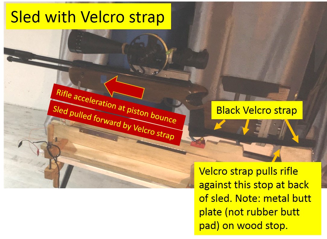
Fig. 9.1 Photo of sled recoil system. The rifle is pulled back against the rear stop of the sled using the Velcro strap. When the rifle accelerates forward with hundreds of gs at the piston bounce, it will pull the sled forward with the Velcro strap, stretching the strap. Please note that in this system we are measuring the velocity of the sled.
Figures 9.2 and 9.3 show the new cradle that I recently built. The top part of Fig. 9.2 shows the overall setup. The rifle recoils in a stationary cradle under the forearm of the rifle. The forearm of my DIY LGU stock is rectangular, so it’s very easy to support it with two blocks of wood. The permanent magnet is attached directly to the rifle via a scope base on the scope rail and the pickup coil is positioned using steel rods to be directly behind the magnet. I’ve added a DIY contact microphone (https://www.instructables.com/Make-a-Contact-Microphone/) on the receiver near the trigger. This serves two purposes. First, it provides a strong and reliable signal to trigger the oscilloscope. The clicking of the sear when the trigger is pulled, creates a sound that is picked up by the microphone and this signal is used to let the oscilloscope know when to start taking data. This is the first time that I used a rifle trigger to trigger an oscilloscope! The microphone also provides useful insight into what is going on inside the rifle. For example, it literally hears not only when the sear falls, but also when the piston bounces and when it lands at the front of the compression tube. In front of the rifle is my DIY chronograph with its two light gates (LG1 and LG2). When the pellet passes through LG1 and LG2, positive voltage pulses are produced that are recorded on the oscilloscope. The time interval between these two pulses can be used to determine the pellet velocity using the fact that the gates are 1.88 ft apart. Once we know the pellet velocity, we can determine the time it took the pellet to travel the 6” distance from the muzzle to LG1. This time is subtracted from the time when the LG1 pulse occurs, allowing one to determine the time when the pellet exits the air rifle muzzle. Since we know when the sear falls using the microphone signal and when the pellet exits the muzzle using the light gate signals, we can determine the pellet dwell time in my LGU, which was around 10.0 ±0.3 milliseconds. The bottom part of Fig. 9.2 shows a close-up of the cradle channels, which are lined with plastic pieces that were cut out from furniture slider pads to provide low friction contact with the stock. The width of the channels is adjustable.
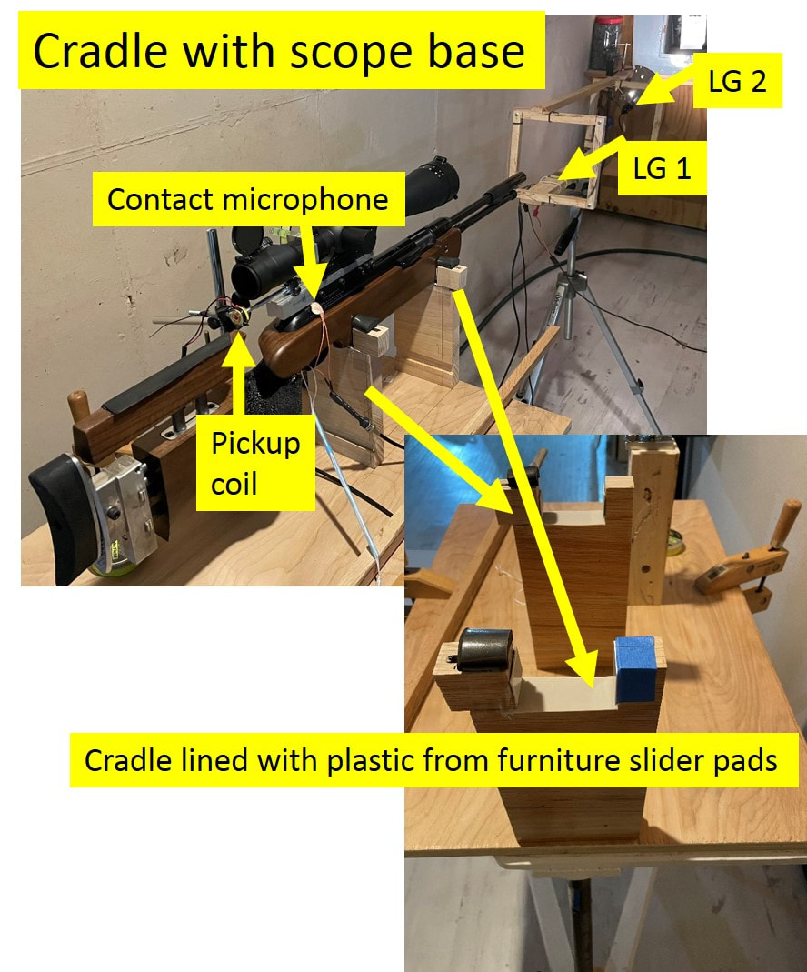
Fig. 9.2 The overall setup using the new cradle system is shown at the top of this figure. The pickup coil is placed behind the permanent magnet, which is attached to the rifle’s scope rail using an aluminum rod and a modified scope base. A DIY contact microphone is mounted on the receiver near the trigger. In front of the rifle is my DIY chronograph with its two light gates, LG1 and LG2, which are used to measure the pellet exit time. The rifle slides in the two cradle supports. A close-up photo of the cradle supports is shown in the bottom of the figure.
Figure 9.3 shows a close-up of the recoil measurement system. The permanent rare-earth magnet is glued to the end of an aluminum rod, which is screwed into a modified scope base that is attached to the rifle’s scope rail. The system easily can withstand over a hundred pounds of force and still remain securely attached to the rifle. Of course, since the combined mass of the scope base, aluminum rod, and magnet is only 30.0 grams, only about 13.5 pounds of force are required to accelerate them in unison with the rest of the rifle, even if the rifles accelerates with 2000 m/s2 (over 200 gs!). The pickup coil is stationary and is positioned directly behind the permanent magnet. I used rods and clamps to allow the position and orientation of the pickup coil to be securely and easily changed, which will help when different rifles are placed in the cradle.
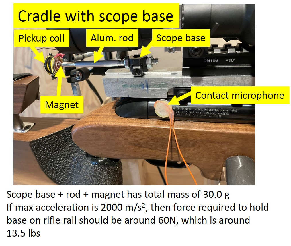
Fig. 9.3 A close-up photo of the velocity measurement system for the new cradle setup. The pickup coil is placed behind the permanent magnet, which is attached to the rifle’s scope rail using an aluminum rod and a modified scope base.
Figure 9.4 shows the old and new recoil traces. On the left one can see the recoil that was measured with the old sled system. The red trace in the middle shows the sled velocity as a function of time. The orange trace right below it shows the light gate signal, with the red vertical lines indicating when the pellet exited the muzzle. The top graph shows the position of the sled vs. time and the bottom graph shows the acceleration vs. time. The right part of Fig. 9.4 shows the recoil traces that were obtained using the new cradle system. In addition to the position, velocity, and acceleration of the rifle itself, I also plot the contact microphone signal at the top. The microphone signal shows a large initial pulse (trigger sear noise), then a smaller pulse (piston bounce, PB), and then two large pulses (piston landing at the front of the compression tube for the first time PL1, bouncing back and then landing again PL2). We can learn a lot when we just listen!
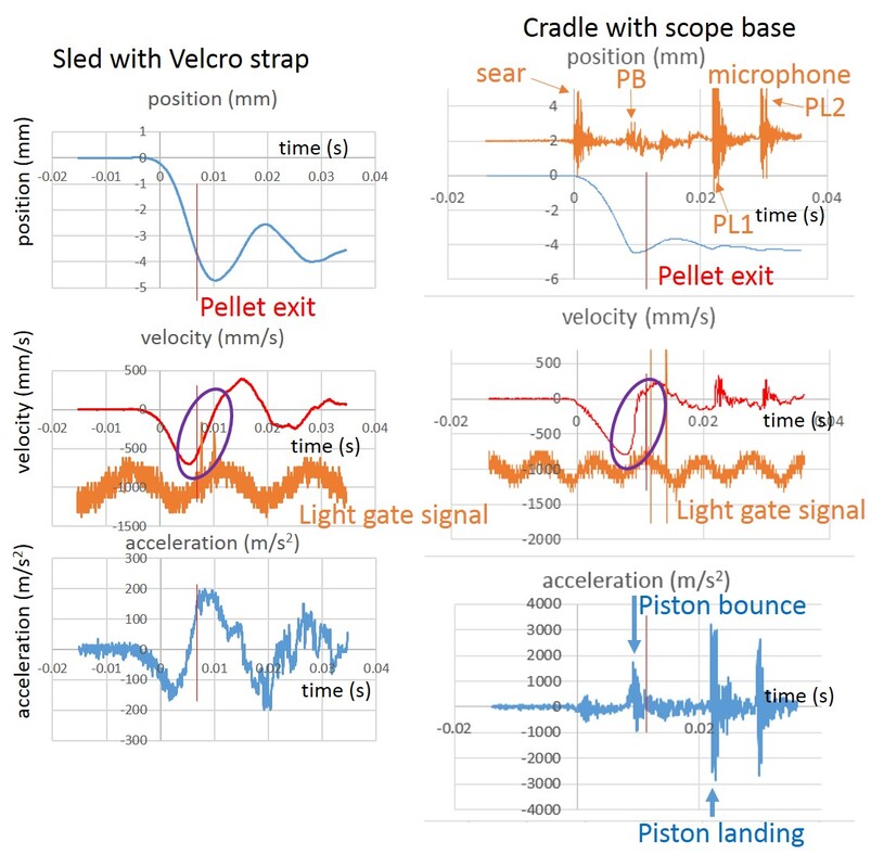
Fig. 9.4 Recoil traces using the sled on left, and the new cradle setup on the right. In addition to recording the velocity of the sled or rifle, from which position and acceleration are determined, we also record the light gate signal to determine when the pellet exits the muzzle. With the new cradle system, I also simultaneously recorded the signal from the contact microphone, which is plotted at the top of the right column. The microphone allows one to “hear” the sear breaking, the piston bounce (PB), and the first and second piston landings (PL1 and PL2).
The velocity and position traces are qualitatively and even quantitatively similar using the two measurement systems. With the sled system, the position trace is much more rounded, smoother and the dips are shifted to longer times. Also, the sled goes back 4.5 mm before stopping while with the cradle system the rifle goes back only 4.0mm. Another difference is that the sled goes forward a much greater distance after the first stop compared to the rifle in the cradle. The sled almost gets halfway back to its starting position, while the cradled rifle moves forward less than a millimeter after the initial stop. The greater movement of the sled is probably due to the lower friction in moving the sled compared to moving the rifle in the cradle. The smoother, rounder, and delayed dips are due to slop in the connection of the rifle to the sled via the Velcro strap, as will be discussed below.
The red velocity traces in the middle of Fig. 9.4 also are similar, with an initial dip as the rifle and sled recoil backwards, a forward peak as the rifle and sled move forward, and some oscillations after that. The maximum rearward velocity of the sled is around 750 mm/s, which is similar to the value obtained using the cradle. This is probably due to the strong connection of the rifle to the sled when the rifle is pushing back. On the other hand, the first dip in the velocity with the sled is symmetric while the right side of that same dip is much steeper with the cradle system (see purple ovals in Fig. 9.4). Furthermore, the magnitude of the peak forward velocity using the sled system is about a factor of two bigger than with the cradle system! The most critical difference is that the pellet exit time with the sled occurs before the sled stops (v=0), while it occurs after the rifle stops using the cradle system. The reason for this is that with the sled, the rifle stops and starts moving forward well before the sled gets accelerated forward by the stretched Velcro strap. As a result, the sled stops after the rifle stops, so the zero in the sled velocity occurs later, after the pellet has exited the muzzle. The pellet actually exited the muzzle after the rifle stopped, but since we’re measuring the motion of the sled and not the rifle, we do not measure this correctly. This is probably the biggest problem with using the sled. The extra forward motion of the sled could be due to the stretched Velcro causing the sled to snap forward and hit the back of the rifle, giving the system a delayed, extra push forward. The lower friction of the sled could also allow the amplitudes of the position and velocity oscillations to be bigger compared to the rifle sliding with more friction on the cradle.
The bottom traces in Fig. 9.4 show the acceleration of the sled (left) and the rifle in the cradle (right). Here the differences are most dramatic. The slop in the connection between the rifle and the sled, especially when the rifle is going forward and relies on the Velcro strap to pull the sled forward, results in broader peaks and dips with much smaller magnitudes. The peak forward acceleration at the piston bounce with the sled is around 200 m/s2 while it’s closer to 1500 m/s2 with the cradle! Thanks to the new cradle data, we can see that the piston landing is more violent (louder, as seen in the top microphone trace, and with a bigger acceleration) than the piston bounce. I guess a cushion of compressed air is gentler in stopping the piston than the steel end of the compression tube! It's very helpful to measure the sound in addition to the velocity and pellet exit signals. The more we can measure the less we have to guess about what is going on!
The problems with the sled system will corrupt the recoil traces, especially the acceleration. However, since we use the same sled system to characterize and compare all three air rifles, the relative differences in recoil behavior can still provide insight into their behavior. Ideally, we would use the new cradle system for all these measurements, but that will have to be a future project.
Although I strive to learn from other people’s mistakes, I often learn more from my mistakes than from my successes, and this mistake has been very educational! My understanding of how an air rifle recoils and how to measure it has dramatically improved thanks the revelations that Steve made!
So here are the conclusions, finally!
This series of chapters has been a long journey for me, that is still ongoing. I have learned a great deal, but still have a lot to learn. I have drawn four basic conclusions from this work:
1. Airguns are fascinating! You probably wouldn’t have made it through the last eight chapters if you didn’t agree with this, but I have gained an even greater appreciation for the engineering and physics involved in air rifles. I’m still amazed that a bouncy mechanical system can put 10 pellets within a quarter inch of each other at 20 yards. The spread of pellet impacts corresponds to an angular separation of less than 0.02 degrees. That’s an angular resolution of 1 part in 18,000! Even more remarkable is the fact that my forty year old FWB 124, with its break barrel, can match the accuracy of modern underlever air rifles, built in this century! For a break barrel to achieve this kind of accuracy, the muzzle of the barrel needs to repeatably return to the same position within 0.006” when the barrel is closed. And this is done with a simple ball detent to lock the barrel in place. I wouldn’t be surprised if most barrels have a runout from one end to the other that is at least a few thousandths of an inch. This accuracy is achieved in spite of fairly violent recoil motion, with the rifle moving almost a centimeter back before the pellet leaves the barrel in the artillery hold. Figure 9.5 shows some of the best 10-shot groups that I have ever shot from a springer at 20 yards. In Fig. 9.6 you can see how my LGU did at 52 yards outdoors. The groups all have a similar POI, especially the first and third groups, which are right on top of each other. These groups would be pretty respectable for a 22 rimfire rifle, so I’m very happy and a bit surprised by the performance of my LGU at 52 yards.
1. Airguns are fascinating! You probably wouldn’t have made it through the last eight chapters if you didn’t agree with this, but I have gained an even greater appreciation for the engineering and physics involved in air rifles. I’m still amazed that a bouncy mechanical system can put 10 pellets within a quarter inch of each other at 20 yards. The spread of pellet impacts corresponds to an angular separation of less than 0.02 degrees. That’s an angular resolution of 1 part in 18,000! Even more remarkable is the fact that my forty year old FWB 124, with its break barrel, can match the accuracy of modern underlever air rifles, built in this century! For a break barrel to achieve this kind of accuracy, the muzzle of the barrel needs to repeatably return to the same position within 0.006” when the barrel is closed. And this is done with a simple ball detent to lock the barrel in place. I wouldn’t be surprised if most barrels have a runout from one end to the other that is at least a few thousandths of an inch. This accuracy is achieved in spite of fairly violent recoil motion, with the rifle moving almost a centimeter back before the pellet leaves the barrel in the artillery hold. Figure 9.5 shows some of the best 10-shot groups that I have ever shot from a springer at 20 yards. In Fig. 9.6 you can see how my LGU did at 52 yards outdoors. The groups all have a similar POI, especially the first and third groups, which are right on top of each other. These groups would be pretty respectable for a 22 rimfire rifle, so I’m very happy and a bit surprised by the performance of my LGU at 52 yards.
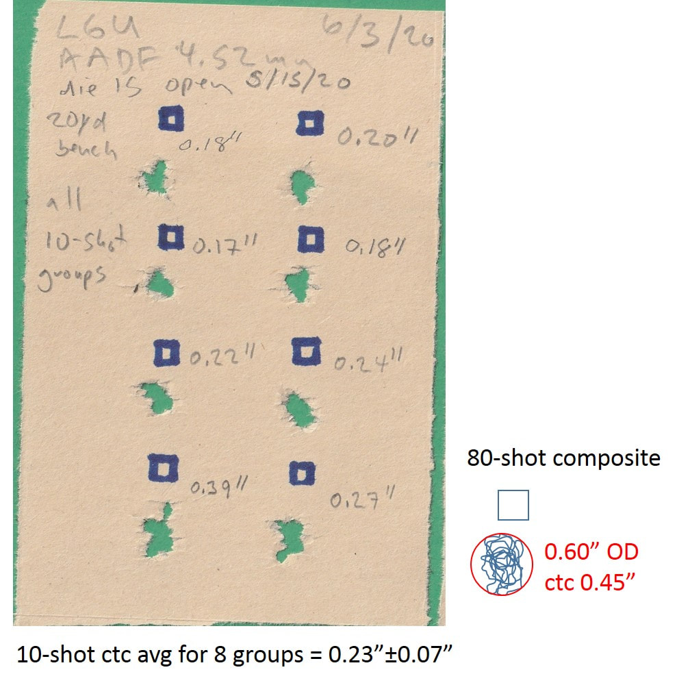
Fig. 9.5 Eight 10-shot groups from my LGU off the bench at 20 yards. The composite group on the right overlays all the groups on top of each other using the aiming square and demonstrates that all eighty shots landed inside a circle with a diameter of 0.60”. The ctc distance for the 80-shot group was a 0.45”.
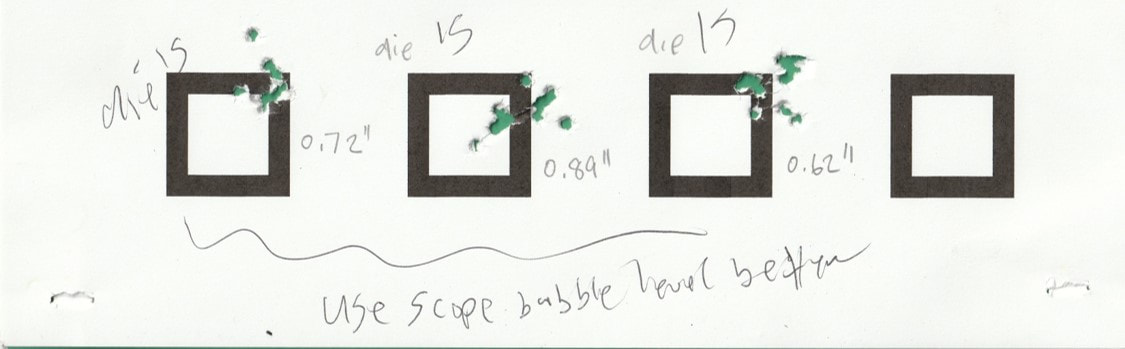
Fig. 9.6 Some more recent groups from my LGU off the bench at 52 yards. These are 10-shot groups, with ctc distances of 0.72”, 0.89”, and 0.62”.
2. Don’t trust a single target group! The computer simulations and more extensive target testing has convinced me that one cannot judge the accuracy of a rifle based on a single group. Completely random fluctuations can easily produce tiny groups, especially if the group consists of five shots, but also for 10-shot groups. I also learned that my simple ideas of statistics do not apply to groups at a target. The group size does not grow simply as the square root of the number of shots, as one would expect for a normal distribution. In hindsight, this makes complete sense since all rifles have a point of impact envelope (POIE) in which they can pretty much keep all their shots, so we should not expect group sizes to simply grow without limit as the number of shots in the group increases.
Figure 9.7a) shows four 10-shot groups at 20 yards from my LGU. The first three groups are pretty typical, but the last had a ctc of around 0.090”. This is pretty remarkable, but unfortunately does not reflect what I can normally expect out of this rifle. If we can get a remarkably small group for 10-shot groups, mostly by accident, the likelihood for getting a tiny but non-representative 5-shot group is even greater. Figure 9.7b) shows largest and smallest five-shot groups out of a total of twenty groups that were generated completely randomly on a computer. One can pretty easily get a difference of nearly a factor of two in group sizes for purely random groups, so when I get a super tiny five-shot group, I have to wonder if it may have just been luck.
Figure 9.7a) shows four 10-shot groups at 20 yards from my LGU. The first three groups are pretty typical, but the last had a ctc of around 0.090”. This is pretty remarkable, but unfortunately does not reflect what I can normally expect out of this rifle. If we can get a remarkably small group for 10-shot groups, mostly by accident, the likelihood for getting a tiny but non-representative 5-shot group is even greater. Figure 9.7b) shows largest and smallest five-shot groups out of a total of twenty groups that were generated completely randomly on a computer. One can pretty easily get a difference of nearly a factor of two in group sizes for purely random groups, so when I get a super tiny five-shot group, I have to wonder if it may have just been luck.
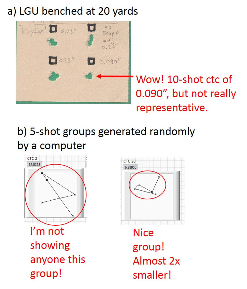
Fig. 9.7 a) A tiny group and some more typical groups from the same rifle under identical conditions. b) A big and a tiny group randomly generated by a computer under identical conditions. My LGU has produced groups as small as 0.090” at 20 yards, but I’m afraid that this isn’t typical. If I create 5-shot groups on a computer, there’s a pretty good chance one group ends up being half the size of another group.
3. Physics and math let us see what is normally unseen! It’s fun to tinker with and shoot air rifles, but it’s even more exciting and interesting to try to understand their behavior in more detail. The recoil of these rifles is complex. I found it especially exciting that some basic analysis of the overall recoil of the rifle gave us important quantitative information about what the piston, which is hidden inside the receiver tube, is doing. For example, we can estimate the piston speed as a function of time. If we had better data and analysis on what the mainspring is doing we could even obtain the piston position as a function of time. This in turn can give us the pressure and temperature of the air inside the compression chamber on a sub-millisecond time scale. I also learned that the pellet leaves the barrel in about 10 milliseconds, right when the piston is making an abrupt stop near the front of the compression chamber. Although we like to have smooth, buzz free spring piston air rifles, the strong recoil oscillations after the pellet leaves the barrel do not affect accuracy, so maybe we shouldn’t worry about them as much? I also hope that these chapters help remove some of the stigma associated with tools that shoot projectiles! My family and I spent a year in Munich Germany a few years ago and my son’s choir group went on a field trip to an airgun club to shoot airguns at 10 meters. It would be hard to imagine something like this happening in the USA! One of the senior choir teachers was an avid air rifle competitor and she made it clear that the airguns in her club were not weapons but were really sports equipment. There are quite a few Olympic sports such as the biathlon, archery, fencing, and of course target shooting that have martial origins, but now are highly competitive and demanding athletic endeavors. Airguns are also widely used for hunting. Of course, airguns can be dangerous, but when they are handled responsibly, they can be extremely beneficial, and can perhaps even be used to learn (and appreciate!) physics and engineering!
Figure 9.8 shows the position, velocity, and acceleration of an air rifle as a function of time. It also shows when the pellet left the barrel and records the sounds that the rifle made. There’s a lot of complex and interesting information here, but the challenge is to figure out what it all means!
Figure 9.8 shows the position, velocity, and acceleration of an air rifle as a function of time. It also shows when the pellet left the barrel and records the sounds that the rifle made. There’s a lot of complex and interesting information here, but the challenge is to figure out what it all means!
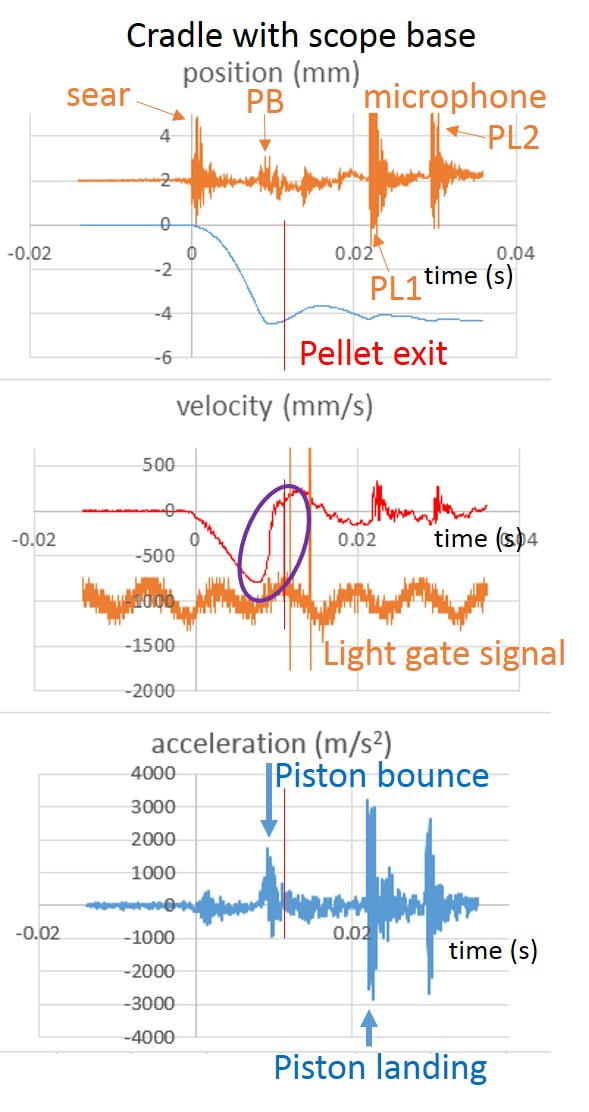
Fig. 9.8 By measuring the velocity of the recoiling rifle as a function of time using a pick up coil, one can “see” how the rifle moves when it is fired. Using the new cradle system, I measured velocity of the rifle in the center plot, and using calculus was able to determine the position (top plot) and acceleration (bottom plot) of the rifle as functions of time with sub-millisecond time resolution. I also record the light gate signal to determine when the pellet exits the muzzle. Using the contact microphone signal (plotted at the top), one can also “hear” the sear breaking, the piston bounce (PB), and the first and second piston landings (PL1 and PL2).
4. It’s the people! I’m glad that I wasn’t alone on this journey of exploring air rifles, and in fact if it weren’t for my fellow air rifle shooters whom I’ve befriended over the years, I’m sure that these chapters would never have been written! I had a lot of fun working with Hector and Willem on these chapters over the past year and really appreciate their help in making sense of it all.
I have greatly enjoyed and benefitted from talking with fellow airgunners from all over the world. A great example was my experience at my first Pyramyd Cup in 2019 (see Fig. 9.9). I was having some technical problems with new equipment and at the end of the first day of competition, many of the people that I was competing against spent their limited free time to help me. Several of these people were national and international champions in FT, so it was wonderful (albeit a bit embarrassing!) to have a group of FT veterans working with me to get the technical problems sorted out before the match continued on the second day.
I have greatly enjoyed and benefitted from talking with fellow airgunners from all over the world. A great example was my experience at my first Pyramyd Cup in 2019 (see Fig. 9.9). I was having some technical problems with new equipment and at the end of the first day of competition, many of the people that I was competing against spent their limited free time to help me. Several of these people were national and international champions in FT, so it was wonderful (albeit a bit embarrassing!) to have a group of FT veterans working with me to get the technical problems sorted out before the match continued on the second day.
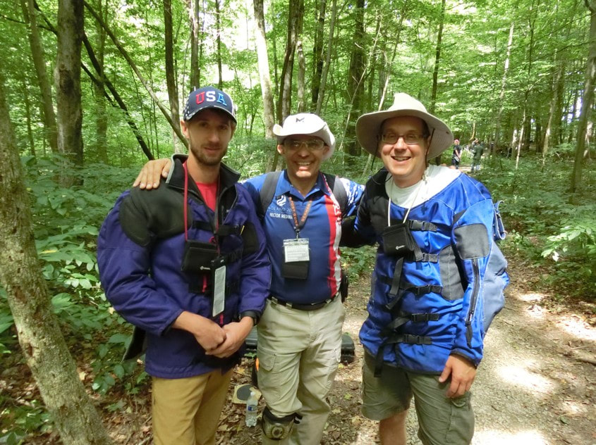
Fig. 9.9 Photo of Nathan, Hector, and me at the Pyramyd Cup in 2019.
I’ve also made some valuable new friends as a result of this blog! I’ve enjoyed some very technical and informative discussions with Steve in NC. Thanks to his excellent questions, I’ve learned a lot more about how springers work and how to measure their behavior. Thanks to this blog, I’ve established a connection with one of my springer heroes, Jim Tyler. Jim has been an inspiration in my work on testing springers. All my recoil measurements are based on the system that he invented, and in the final measurements I used a recoil cradle just like he's been doing for many years. I have read all his Technical Airgun articles in Airgun World since 2009, which is as far back as I can get in the digital archive. Jim has probably forgotten more than I will ever know about springers, and yet he has been extremely gracious, friendly and modest in all the excellent help that he has given me.
I hope that you have found these chapters interesting and that they stimulate more discussions and new friendships!
JC
Aug/2021
I hope that you have found these chapters interesting and that they stimulate more discussions and new friendships!
JC
Aug/2021
 RSS Feed